MENU
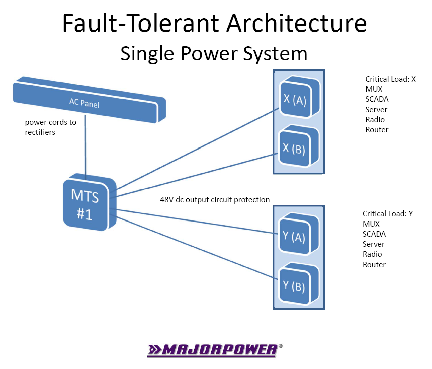
The simple configuration employs a power shelf and two or more circuit protection devices, for example fuses or circuit breakers. A single power shelf system can support many A/B loads when the current requirements are low and the adequate protection devices are installed.
Alternating-current (ac) diversity is managed through individual power module cord connections. Consideration given to each source of the “mains” connection can increase the fault-tolerant design. For example, one ac source might be directly connected to house mains and the second source might be connected to an uninterruptible ac power appliance.
Power modules installed in a common system shelf share the direct-current (dc) bus connection. The aggregated dc power is then distributed to the source side of protection circuit devices. A specialized apparatus is connected to the load side of each protection device. When the overall load power requirement, called “N”, is within the rating of one power module, a system will be considered an N+1 design. As a concept, N refers to the load support using one power module and the second power module is effectively in a hot-standby ready status. Reality being that power modules share the bus, therefore, both support a portion of the load requirement until such time a fault condition (IE: one power module off) will cause a single power module to supply power to a full load.
Individual circuits, called A/B, from a distribution panel isolate the connection from the power system to either of the apparatus loads. Multiple connections work to eliminate single element failures, whether in a material defect or unintentional cable pull action by personnel.
A load-based configuration will analyze the current draw of each load apparatus connected to a protection circuit. Apparatus can be added to the power system until the aggregate current is slightly less than the capacity of a single power module, if a N+1 configuration is implemented. Apparatus can be added to the power system until the aggregate current is near the total capacity of the power system, provided this is the design engineer’s intended operation. Risk analysis will vary between applications.

Picture power system protective devices connected to the A and B inputs of a load utilizing individual circuits. The connections facilitate isolated and multiple paths for dc power support. The A/B dc support path is now established through two connections to the single power supply systems.
The level of fault-tolerant power protection design is increased when the power supplies are installed with redundant power modules and separate ac input circuits. These ac input circuits would conceivably originate from diversified ac service panels or data-center back-up power systems.
#FaultTolerantPower